Today's steel processing industries, such as the automotive, household appliance and construction industries, sometimes use coil-coated sheet steel before the processing stage. The problem with this material after …
Today's steel processing industries, such as the automotive, household appliance and construction industries, sometimes use coil-coated sheet steel before the processing stage. The problem with this material after cutting or punching is that the cut surfaces are uncoated. The aim of this project was to develop a process for applying a high-quality cut surface coating made of corrosion protection paint that can be cured under ultraviolet light (UV) for moulded steel strip parts that have to meet the highest corrosion protection and visual requirements. The development of the cut surface coating process included the investigation of several coating methods.
For long parts, the cut surfaces were coated by rolling on the anti-corrosion paint, while a stamping process and an electrostatic spraying process were used for 3D moulded parts. The stamping process used a stamp adapted to the cut surface of the component, which was wetted by immersion in a heatable paint container. This method of stamp wetting and the reduction in paint viscosity through heating enabled a high process speed and an improvement in coating quality. By using UV-curable anti-corrosion paint, the cut surface coating could be cured within a few seconds. Gardo® Protect UV anti-corrosion coatings were used in the development of the coating processes. With the coating by rolling, pre-galvanised slit strip with a thickness of d = 2 mm could be provided with effective cut surface corrosion protection at a speed of 5 m/min. The process thus offers the possibility of integrating the cut surface coating into production systems for the manufacture of long parts that are subject to forming at low speeds, e.g. roof or façade parts. The coating tests at higher speeds (> 5 m/min to 80 m/min) showed insufficient corrosion resistance of the cut surface coating. It is assumed that the coating concept can be realised at coating speeds of > 30 m/min by improving the system design and adjusting the rheology of the anti-corrosion paint. In a first step, the stamping method was applied to a stamped/bent part in order to investigate the corrosion protection properties of the cut surface coating. The cut surface coating of the component had a layer thickness of between 60 μm and 230 μm with a paint quantity of 0.35 g/m in relation to the cut surface length. The corrosion resistance was tested using a salt spray test (DIN EN ISO 9227, 2016 h), VDA alternating test (VDA 621-415, 20 cycles) and the DaimlerChrysler climatic alternating test (KWT-DC, 12 weeks). A further development of the stamping process was used to demonstrate the applicability of the method for the cut surface coating of 3D moulded parts on a stamped/pressed part (fuel filler flap). The stamping process achieved a cycle time of around 10 s when coating the cut surfaces of the fuel filler flap. The cut surface protection had a layer thickness of between 116 μm and 288 μm with a paint quantity of 0.47 g/m in relation to the cut surface length. The corrosion resistance was tested using a salt spray test (DIN EN ISO 9227, 2016 h) and VDA alternating test (VDA 621-415, 15 cycles).
Payment by card (Stripe) or invoice (DE, AT, CH). Download link by email: automatically after ordering by card, after order approval for invoice (valid for 30 days). Terms
Machine-translated title and description. The document itself is in German.
Digital download
Other parts and editions as well as neighbouring documents of the same series.

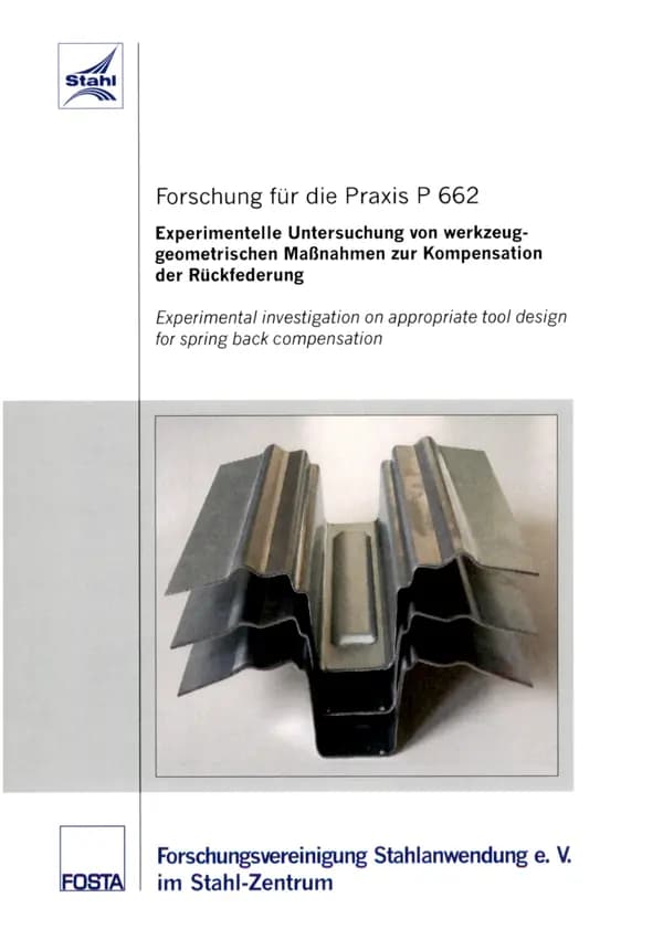
P 662 - Experimental investigation of mould geometry measures for springback compensation The demand for greater accuracy of car body parts is accompanied by increasing geometric and material complexity of the components. The complexity of the workpieces and the behaviour of high-strength multiphase steels (e.g. TRIP steels) make it difficult to predict the springback numerically and to control it reliably. Targeted geometric design of the active mould parts and the component geometry during the The aim is to achieve a reduction and compensation of springback through targeted geometric design of the active mould parts and the component geometry during the main forming process. The investigations in this research project focussed on the high-strength sheet metal material HCT690T, which was provided by three different manufacturers. The behaviour was examined, evaluated and validated on real demonstrator components using realistic model tests, taking into account the influencing variables. Based on an analysis of the state of the art, an evaluation of the workpiece and tool geometry measures was carried out and relevant geometries were specifically examined in the model tests. For the model tests, 2 test tools with geometric features similar to structural supports were used. These were a straight U-profile and a curved top-hat profile. The relevant geometries analysed were die steps, die radii, base fields/combining and drawing bars. The influence of hold-down force, lubrication and blank geometry were also analysed. The investigation of this large number of influencing variables required the use of statistical test planning methods. Following the experimental tests, the components were geometrically measured using optical measuring methods and the influence on the springback behaviour was determined in comparison with the target geometry. After an evaluation of the springback-reducing measures, the results were transferred to the demonstrator component, which in this case was a reinforcement part of a strut brace. Within this component, different geometric variants were analysed and assessed with regard to their springback. The material tests on the HCT690T were able to show the change in the modulus of elasticity with increasing pre-strain of the tensile specimen. For multiphase materials, this can be seen as one of the main causes of the increasing springback problem. Within the model tests, matrix steps, drawing bars and base fields proved to be an effective means of reducing springback in straight components. For curved profiles, the mould radii proved to be the most effective way of reducing springback. In the tests on the demonstrator component, the limited transferability of the results from the model tests could be proven and thus an improvement in springback could be achieved. Authors: R. Neugebauer, T. Lieber Publication: 2008
available anytime
€30.00
excl. VAT

P 667 - Gas-shielded welded steel structures of low wall thickness from the automotive industry" in the cluster "Applicability of strength concepts for welded components subject to vibration loads Today, the nominal stress, structural stress and notch stress concepts are mainly used to estimate the service life of welded joints subjected to vibration. The aim of the AiF cluster "Applicability of strength concepts for welded components exposed to vibration" was to analyse the available strength concepts: - Investigate the available strength concepts with regard to application limits and reliability as well as consistency and compatibility, the - increasing the accuracy of service life estimates for welded components and simplifying the - simplifying the selection of the most appropriate design concept. Applications from the rail vehicle, automotive, mechanical engineering and shipbuilding industries were investigated in 6 projects in 5 research institutes, funded by 5 member organisations of the German Federation of Industrial Research Associations (AiF), Figure 1.1. Nine components were examined in detail. Frequent meetings of experts were held to coordinate and exchange experiences across the various sectors. Publication: 2015 Authors: DVS Prof. Dilger
available anytime
€30.00
excl. VAT

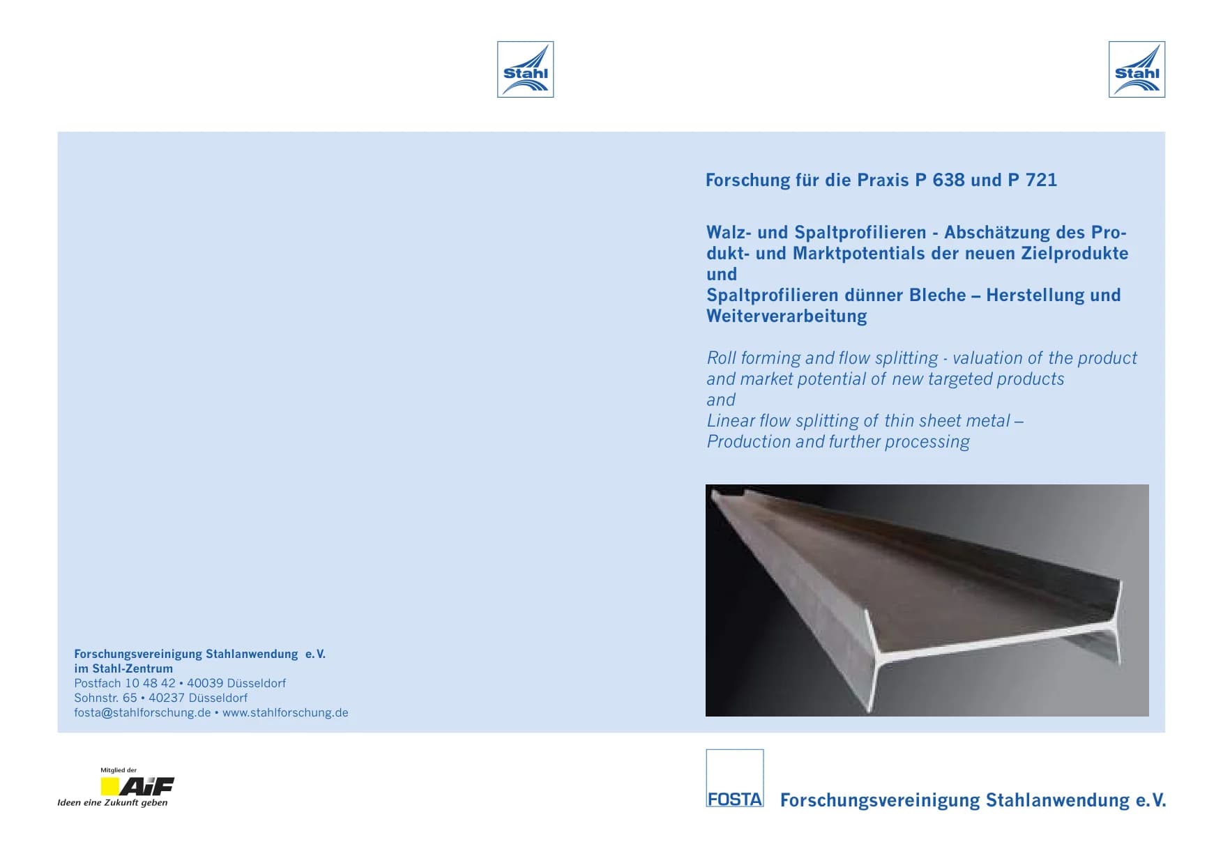
P 638 - Roll and gap profiling - Assessment of the product and market potential of the new target product As part of current endeavours to advance the development and application of lightweight construction strategies, the main objective is to achieve increasingly higher component strengths with decreasing material volumes and to be able to cover critical component areas with weight-reducing materials in the future. In addition to the development of high-strength and ultra-high-strength materials as part of lightweight material construction, efforts are also being made in lightweight mould construction to reduce the sheet thickness while maintaining the same component properties. However, one problem with weight reduction is component failure due to buckling or buckling caused by instabilities. An effective design element for shifting this instability limit towards higher loads is the introduction of bifurcations. With the help of the gap profiling process, a forming process has been developed that allows branches to be realised on the strip edge of sheet metal, which was previously only possible by doubling material within die bending or roll forming processes. In addition to the effect of increased profile rigidity, it is possible to utilise branches for new, load-adapted joining strategies. Furthermore, the downstream processing of branched profiles opens up a wide range of new functional profile applications. As part of the activities of the "Roll and gap profiling" working group, the process development of gap profiling was advanced through the realisation of a new type of tool concept. A hydrostatic compressive stress state is induced in the workpiece through a targeted arrangement of nip and auxiliary rollers, which increases the material's ability to change shape and leads to the formation of branches, so-called flanges, on the edge of the sheet metal strip. The results obtained during development were presented using the example of two micro-alloyed fine-grained steels. It was possible to produce branches with a span of approx. 30 mm. The splitting profiles have a macroscopically crack-free surface as well as a significant hardening gradient, starting from the surface facing the splitting rollers. Based on this, it is possible to further process the slit profiles using forming technology. Die bending and roll forming processes can be used to create functional multi-chamber profiles which, in addition to increased rigidity, buckling and buckling stability, also offer the possibility of functional integration. As part of the working group's activities, the roll forming of gap profiles into a single-chamber profile was investigated in particular. Conventional tools for designing roll forming processes cannot be used due to the fact that branches cannot be modelled. Instead, the process was modelled and analysed using FE systems. Furthermore, aspects of tool design and layout were investigated that arise when profiling branched semi-finished products due to the occurrence of undercuts. The single-chamber profile realised as part of the working group demonstrates the possibilities opened up by a process chain consisting of gap and roll forming: The process limits of slit profiling allow the geometry of the semi-finished product slit profile for subsequent forming to be varied over a wide range, enabling the production of thin-walled, integrally branched multi-chamber profiles of variable geometry with free flanges. Prospective opportunities therefore lie in particular in the realisation of innovative, multifunctional products with advantages that affect both their properties and the production possibilities and costs. The activities of the Rolling and Gap Profiling Working Group are being continued as part of the transfer project "Control of tolerance fields in gap and roll profiling" within the framework of the SFB 666. The main objectives of this project are to analyse accuracy and tolerances in order to derive industrially feasible product classes and, based on this, appropriate strategies for the process-reliable design of a continuous process chain for slitting and roll forming. Authors: P. Groche, D. Vucic, P. Beiter, R. Salomon Publication: 2011
available anytime
€20.00
excl. VAT
Payment by card (Stripe) or invoice (DE, AT, CH). Download link by email: automatically after ordering by card, after order approval for invoice (valid for 30 days). Terms