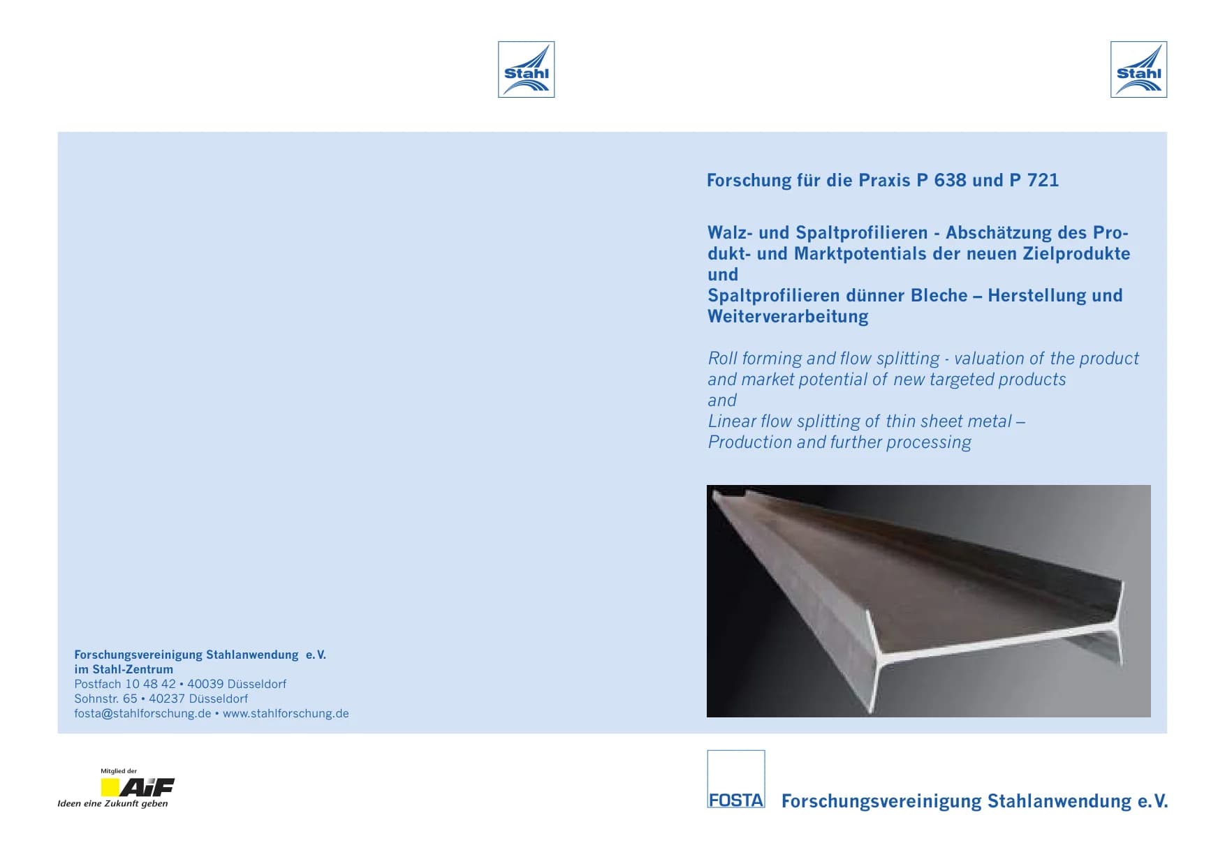
As part of current endeavours to advance the development and application of lightweight construction strategies, the main objective is to achieve increasingly higher component strengths with decreasing material volumes …
As part of current endeavours to advance the development and application of lightweight construction strategies, the main objective is to achieve increasingly higher component strengths with decreasing material volumes and to be able to cover critical component areas with weight-reducing materials in the future. In addition to the development of high-strength and ultra-high-strength materials as part of lightweight material construction, efforts are also being made in lightweight mould construction to reduce the sheet thickness while maintaining the same component properties. However, one problem with weight reduction is component failure due to buckling or buckling caused by instabilities.
An effective design element for shifting this instability limit towards higher loads is the introduction of bifurcations. With the help of the gap profiling process, a forming process has been developed that allows branches to be realised on the strip edge of sheet metal, which was previously only possible by doubling material within die bending or roll forming processes. In addition to the effect of increased profile rigidity, it is possible to utilise branches for new, load-adapted joining strategies. Furthermore, the downstream processing of branched profiles opens up a wide range of new functional profile applications. As part of the activities of the "Roll and gap profiling" working group, the process development of gap profiling was advanced through the realisation of a new type of tool concept. A hydrostatic compressive stress state is induced in the workpiece through a targeted arrangement of nip and auxiliary rollers, which increases the material's ability to change shape and leads to the formation of branches, so-called flanges, on the edge of the sheet metal strip. The results obtained during development were presented using the example of two micro-alloyed fine-grained steels. It was possible to produce branches with a span of approx. 30 mm. The splitting profiles have a macroscopically crack-free surface as well as a significant hardening gradient, starting from the surface facing the splitting rollers. Based on this, it is possible to further process the slit profiles using forming technology. Die bending and roll forming processes can be used to create functional multi-chamber profiles which, in addition to increased rigidity, buckling and buckling stability, also offer the possibility of functional integration. As part of the working group's activities, the roll forming of gap profiles into a single-chamber profile was investigated in particular. Conventional tools for designing roll forming processes cannot be used due to the fact that branches cannot be modelled. Instead, the process was modelled and analysed using FE systems. Furthermore, aspects of tool design and layout were investigated that arise when profiling branched semi-finished products due to the occurrence of undercuts. The single-chamber profile realised as part of the working group demonstrates the possibilities opened up by a process chain consisting of gap and roll forming: The process limits of slit profiling allow the geometry of the semi-finished product slit profile for subsequent forming to be varied over a wide range, enabling the production of thin-walled, integrally branched multi-chamber profiles of variable geometry with free flanges. Prospective opportunities therefore lie in particular in the realisation of innovative, multifunctional products with advantages that affect both their properties and the production possibilities and costs. The activities of the Rolling and Gap Profiling Working Group are being continued as part of the transfer project "Control of tolerance fields in gap and roll profiling" within the framework of the SFB 666. The main objectives of this project are to analyse accuracy and tolerances in order to derive industrially feasible product classes and, based on this, appropriate strategies for the process-reliable design of a continuous process chain for slitting and roll forming.
Payment by card (Stripe) or invoice (DE, AT, CH). Download link by email: automatically after ordering by card, after order approval for invoice (valid for 30 days). Terms
Machine-translated title and description. The document itself is in German.
Digital download
Other parts and editions as well as neighbouring documents of the same series.

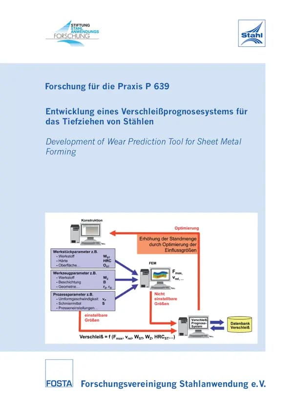
P 639 - Development of a wear prediction system for the deep drawing of steels The manufacture of products from thin sheet metal occupies an important position in manufacturing technology worldwide. Due to the demands for a reduction in CO2 emissions and a reduction in petrol consumption, the automotive industry has reacted with a rapid and effective implementation of the lightweight construction idea in passenger cars. In addition to new developments and forming tests of light metals such as aluminium, titanium and magnesium, the steel industry has developed new, so-called high-strength and ultra-high-strength steels. In order to increase the competitiveness of high-strength and ultra-high-strength steels compared to competing materials such as aluminium or fibre-reinforced plastics, the use of a wear prediction system appears to make sense, as a large part of the production costs are already determined in the tool design. For this reason, a simulation-supported procedure was developed in this research project in order to realise such a wear prediction system with all the necessary work steps. The system is intended to provide the user with information during the design of a deep-drawing tool for high-strength and ultra-high-strength steels. To implement the wear prediction system, extensive tests were first carried out on the institute's own wear test bench. These wear tests made it possible to determine the significance of influencing parameters on wear. In particular, the adjustable influencing variables, such as the material properties, but also the non-adjustable parameters, such as the relative speed, were taken into account. In addition to these basic wear investigations, industrial sheet metal components and their tools were also selected for wear measurements. Only forming processes for high-strength and ultra-high-strength steels were taken into consideration. The tools were measured optically at certain intervals during the project using the ATOS ll measuring system from GOM and the resulting wear was determined in comparison to previous measurements. All parameters that could be determined with the help of the wear test stand and the optical measurement were transferred to a database. This data was used to create a software prototype for calculating the wear on sheet metal forming tools. Geometric data from a CAD system and calculated data from FE software were used for this purpose. Finally, the software prototype developed in this research project was verified by a forming process of a partner of the project committee and a wear calculation was carried out after 285,000 strokes for a selected tool. The calculation showed that the software prototype identifies the wear-relevant areas. For a final application of the system in practice, the system-specific wear coefficient must be determined experimentally for a high number of strokes for each application. It therefore makes sense in future to systematically investigate the effects of certain tribological effects on wear in order to achieve transferability of the wear coefficients to other processes. Authors: B. A. Behrens, R. Salomon Publication: 2011
available anytime
€20.00
excl. VAT

P 636 - COMBRI - Competitive Steel and Composite Bridges by Improved Steel Plated Structures Publication: 2006
available anytime
€30.00
excl. VAT

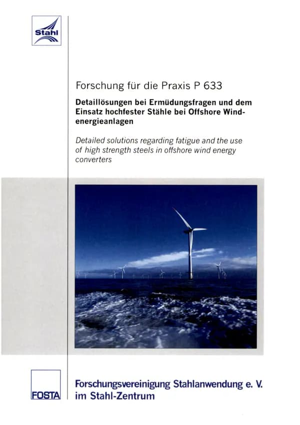
P 633 - Detailed solutions for fatigue issues and the use of high-strength steels in offshore wind turbines The promotion of renewable energies by the German government is causing an enormous upswing, particularly in the wind energy sector. In order to meet the ever-increasing demand, the construction of offshore wind farms is planned in the North Sea, the Baltic Sea and the Irish Sea, as large areas with a higher and more even wind supply are available offshore than on land. However, the conditions here are more difficult due to the great water depths, the large tower and hub heights required as a result and varying site conditions. The aim of this research project was to identify the particular difficulties that arise in terms of stability and durability and to develop new solutions. This includes the selection of the steel grade, the connection technology, in particular questions regarding cylindrical or conical connections, the estimation of the remaining service life and the consideration of problems with corrosion. The design of wind turbines is largely determined by the fatigue strength of critical notch details, especially weld seams. The fatigue strength and thus the service life of these notch details can be significantly increased through the targeted application of suitable weld post-treatment processes. Shot peening, ultrasonic peening (UP) and ultrasonic impact treatment (UIT) were investigated in detail as part of the research project. By combining geometric and mechanical effects, the UP and UIT processes significantly increase the fatigue strength of welded joint details. The results from tensile swelling tests confirm this for welded ring flange segments, butt welds and welded transverse stiffeners with sheet thicknesses of 8 to 30 mm. The ultrasonic methods were also analysed for the possibility of upgrading existing components. The results show that when the method is applied to samples that have been pre-damaged up to the end of their calculated service life, it is possible to increase the residual fatigue strength to the level of components treated immediately after production. For water depths of over 30 metres, the trend for the foundation structures of offshore wind turbines is towards dissolved structures. For this reason, the tripod structure was analysed more closely within this research project. In detail, this concerned the design of the upper central node, which is the most critical detail for the fatigue design of the tripod. Conventional cylindrical tubes and tubes with conical expansion were considered for the design of the upper central node, which represents the connection between the tower and the base struts. In crane construction, such connections are designed with an internal stiffening ring. Inspired by this, a new node design was developed and investigated, whereby the upper central node was designed with a stiffening ring. In the field of corrosion protection, the special aspects of corrosion protection for offshore wind turbines using high-strength steels were discussed. The questions regarding the interaction of coatings with the cathodic corrosion protection, the rust surcharge, the corrosion behaviour in encapsulated systems and the formation of cracks in the steel under the coatings were dealt with in depth. High-strength steel is not a new material for use in offshore support structures and can be used in exactly the same way as the structural steel previously used. Authors: R. Puthli, S. Herion, J. Hrabowski, T. Ummenhofer, I. Weich, T. Faber, M. Lossin, H. Huhn, J. Uecker Publication: 2008
available anytime
€30.00
excl. VAT

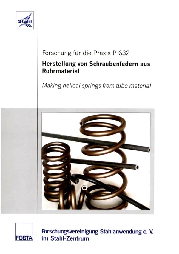
P 632 - Manufacture of coil springs from tubular material Coil springs are essentially subjected to torsion. The material near the wire axis remains largely unutilised. By using tubular material, it is possible to reduce the spring mass by 20 - 40 % while retaining the same spring function. The prerequisite for this substitution is the availability of high-quality tubular material with similar strength properties to spring steel wire. A seamless tube made of 70Mn7 steel was used in the research project. To create the continuous transformation diagrams, the required cooling curves were determined, hardness measurements were carried out and microsections were made to determine the microstructure. The pipe material was available in different dimensions and treatment states. The exact dimensions, surface roughness and mechanical characteristics were determined in the tensile test. Metallographic analyses were also carried out. Based on the results of the wire tempering tests, the temperature range for pipe tempering was narrowed down to tempering temperatures between 350 and 500°C. It was determined that the tube should be formed into a spring in the soft state and then tempered to the desired strength. From the results of roughness measurements, it could be clearly concluded that only drawing with an internal mould leads to an internal surface that is suitable for the production of a dynamically loaded Bourdon tube. In addition, the inside of one part of the tube was peeled between two drawing stages. The final tube dimension was 10 x 2.0 mm. To test the springs, two geometries (w = 8 and w = 5) were produced using two forming technologies: coiling and winding. During coiling, a slight cross-sectional deformation of the tube was observed due to the pressure of the feed rollers and the bending of the tube on the circular arc. The subsequent treatment consisted of hardening the spring, tempering, shot peening and tempering again. The end coils of some of the springs were ground. The heat treatment was carried out in such a way that a strength of Rm approx. 1700 MPa was achieved. The spring test involved determining the characteristic curve, relaxation behaviour and fatigue strength. The latter was intended to show that springs made of tubular material are generally also suitable for use under oscillating loads (influence of the inner surface). The load change tests were carried out with a stroke stress (corrected) of 650 MPa (?ku = 300 MPa, ?ko = 950 MPa). The best test results were achieved with springs with non-ground end coils made of internally peeled tube. Load cycles of up to 14 million were achieved without breakage. The springs made of non-peeled tube showed failures under 100,000 load cycles. The cause of breakage was due to the inadequate quality of the inner surface. In the springs with ground end coils, the end coils broke. Further necessary and promising research directions were identified: ⇒ the use of higher-strength material (high-strength spring steel), ⇒ further reduction of the wall thickness of the tube and thus even greater material savings, ⇒ improving the economic efficiency of pipe production. Authors: G. Lehmann, F. Hoffmann, H. J. Schorcht, S. Lutz Publication: 2007
available anytime
€20.00
excl. VAT
Payment by card (Stripe) or invoice (DE, AT, CH). Download link by email: automatically after ordering by card, after order approval for invoice (valid for 30 days). Terms