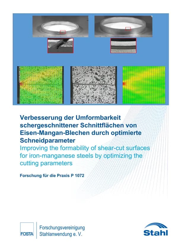
- Hole expansion test with Nakajima punch - Collar tensile test - Diabolo test - Edge fracture tensile test By regularly coordinating the procedure with the project committee, the research objectives were achieved and a …
P1072 - Improving the formability of shear-cut cut surfaces of iron-manganese sheets through optimised cutting parameters Increasing customer requirements and tougher global competitive conditions are presenting manufacturing companies with ever greater challenges. To meet these challenges, known and new manufacturing processes must be combined with a wide variety of materials. In order to achieve weight and volume savings in the end product, high-strength and ultra-high-strength steels are used, among other things. The increased use of modern materials, such as high-strength sheet steel materials, poses new challenges for the stable processing of semi-finished products.
One of these challenges is the sensitivity to edge cracking. The separation process during shear cutting significantly influences the microstructure of the material in the shear zone as a result of localised deformations (Lange 1990; Doege and Behrens 2010). Depending on the sheet material and cutting parameters, the deformed shear influence zone extends up to a few tenths of a millimetre from the cut surface into the base material. This results in a reduction in the residual forming capacity of the shear zone (Gläsner et al. 2013). As a rule, shear-cut edges are subjected to further stress in the subsequent process steps when blanks are formed or, for example, flanges are set aside or cut holes are widened. Cut surfaces are subjected to a flat strain and approximately uniaxial stress state. Particularly when using multiphase high-strength and higher-strength steel materials, it can be observed that cracks occur more frequently during set-down or expansion processes, starting from shear-cut edges (Held et al. 2010; Kardes and Altan 2008). These are known as edge cracks. The formation of cracks is influenced by a variety of factors. Various test methods can be used to determine the susceptibility of a12 material to edge cracking. In addition to the only standardised test method, the so-called hole expansion test according to ISO 16630, the following methods were used to characterise the edge crack sensitivity of high-manganese steels and a dual-phase steel in the research project: - Hole expansion test with Nakajima punch - Collar tensile test - Diabolo test - Edge fracture tensile test By regularly coordinating the procedure with the project committee, the research objectives were achieved and a new edge crack testing method was verified and validated. The objective of the research project was therefore achieved. The research project was carried out at the Chair of Forming Technology and Foundry Engineering at the Technical University of Munich with technical support and financial assistance from the Forschungsvereinigung Stahlanwendung e. V., Düsseldorf, with funds from the Stiftung Stahlanwendungsforschung, Essen.

Payment by card (Stripe) or invoice (DE, AT, CH). Download link by email: automatically after ordering by card, after order approval for invoice (valid for 30 days). Terms
Machine-translated title and description. The document itself is in German.
Digital download
Other parts and editions as well as neighbouring documents of the same series.

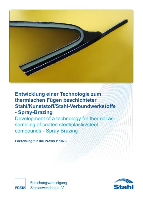
P 1073 - Development of a technology for thermal joining of coated steel/plastic/steel composites - "Spray-Brazing-" The automobile of the future must fulfil the growing social expectations with regard to energy efficiency, fuel consumption, climate protection, safety, comfort and sustainability. Lightweight construction has a special role to play here. Recent developments make it possible for the end user - the mobility manufacturing industry - to work with prefabricated lightweight composite materials, steel-plastic-steel composites. Intelligent utilisation of these new steel-plastic-steel composites requires suitable joining technologies. The aim of the project is therefore to develop a new joining technology for the production of car body components with steel/plastic/steel composites and various materials by using thermal energy in the form of non-transmitted arcs and laser radiation. The aim is to produce metallic, dense linear joints between steel/plastic/steel composites and galvanised steels at joining speeds of up to 4 m/min with the following properties: Tensile strengths > 100 MPa, no delamination of the steel-plastic-steel composite and a uniform concave seam geometry. Delamination of the polymer as a result of the joining process must be avoided. By using arc soldering and laser processes, the advantages of this technology, such as problem-free integration into robot production (high degree of automation), accessibility from only one side (compared to clinching or self-pierce riveting), gap and position tolerance (solidification conditions) and no complex pre-treatment, are to be utilised. as well as no complex pre-treatment and longer fixing times (compared to gluing). As part of this work, liquid jet brazing was developed for the production of metallic, dense, homogeneous connections to steel-plastic-steel composites with extremely thin individual sheet layers. Liquefaction of the brazing filler material, activation of the joint and precise adherence to a temperature regime are required in order to produce delamination-free joints. The use of induction is one way of liquefying the filler material. In order to achieve the desired high brazing speeds of approx. 4 m/min, reliable activation of the joint is required. Laser radiation is suitable for this purpose. In addition to the objective of producing delamination-free joints at high joining speeds, joint strengths that are significantly higher than those of bonded joints were defined as a boundary condition. This could be reliably achieved. Furthermore, a concave seam geometry was achieved. The developed liquid jet soldering process is suitable for producing joints to extremely thin components. Delamination of the steel-plastic bond can be avoided. The strength of the joint is approx. 100 MPa. Corrosive and metallographic tests were also used to characterise the joints produced. All test results were summarised in this paper. Publication: 2016 Authors: R. Winkelmann, A. Kilian, G. Bürkner, K. Alaluss
available anytime
€30.00
excl. VAT

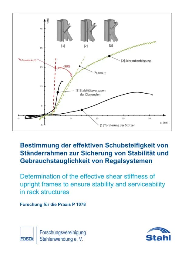
P 1078 - Determination of the effective shear stiffness of upright frames to ensure the stability and serviceability of shelving systems For the construction of high-bay warehouses, truss-type upright frames made of thin-walled, cold-formed steel profiles are generally used. Due to their design, the stud frames have a significantly reduced shear stiffness compared to Engesser's shear theory. To date, the basis for analytical calculation of the shear stiffness has not been available and it is common practice to determine the shear stiffness of the stud frames experimentally. This approach is very cost-intensive and prevents the targeted optimisation of highly stressed rack structures. As part of the present research project, a comprehensive literature review was first carried out. This involved collating the existing findings on the key influencing factors and preparing the basis for the application of the component method. With the help of a total of 73 large component tests, the load-bearing and deformation behaviour of the stud frames was analysed in detail in "horizontal" and "vertical" frame shear tests. Based on the test results and further comparative calculations, it was shown that the pure shear stiffness is independent of the test execution and that the differing results are solely due to the different proportions of global bending deformations. The in-depth knowledge of the load-bearing and deformation behaviour of the stud frames gained in the large-scale component tests helped to identify the main influencing factors and to develop a division of the stud frames into eight components. Stiffness coefficients have been derived for each of these components by analytical or numerical means. Based on Engesser's work, an overall model has been developed that allows the proportional shear stiffness of the stud frames to be combined into an equivalent spring stiffness - analogous to a series connection of springs. With the help of the overall model and the breakdown of the upright frames into eight components, key components can be identified and the upright frames specifically optimised with regard to shear stiffness. As part of the research project, possible optimisation potentials were identified and economic feasibility studies were carried out. For easier application in practice, the overall model has also been prepared for practical construction, the application of which is presented in sample calculations. Publication date: April 2019 Authors: Prof. Dr.-Ing. D. Ungermann, Dipl.-Ing. St. Schneider, A. Pätzold M.Sc.
available anytime
€50.00
excl. VAT

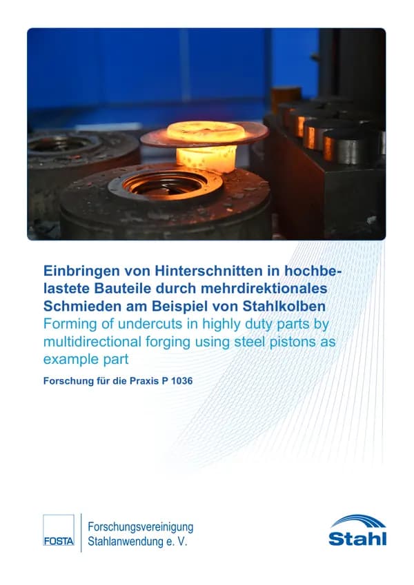
P 1036 - Introduction of undercuts in highly stressed components by multidirectional forging using the example of steel pistons In this AiF project (IGF No. 18162 N), undercut forging was investigated using the example of piston pin bores for steel pistons. In contrast to the conventional forging process for steel pistons, multi-directional forming takes place in the final forming stage, in which the piston pin bores, which represent an undercut, are preformed. To this end, the sequence of stages was first developed virtually with the aid of material flow simulations. A tool concept was then developed to enable undercut forging using a multi-directional tool. With this tool, punches move laterally into the workpiece and deform it further. This tool was designed and manufactured. Various forging tests were then successfully carried out and analysed. The economic efficiency of the process was then assessed and an application guide for the development of undercut forging processes was developed. In this project, the bolt holes in a steel piston could be pre-punched in the forging process for the first time. The advantages of this process are the material savings, improved component properties of the forged part and a faster and simplified reworking process compared to the conventional forging process. The material saving was 5% compared to the standard forging process. The adapted fibre flow in the bore area is likely to be of great importance for the component properties. From an economic point of view, the possibility of accelerated reworking through undercut forging is of the highest relevance. The design of the undercut forging process differs from conventional closed-die forging processes only in the final forming stage. It turned out that the complete punching of the component is associated with too much effort in terms of process technology, so that the pre-punching variant was favoured. The clamping forces required for multi-directional undercut forging are a particular challenge for undercut forging tools. The variants of a force-fit (using springs) and a form-fit closure (using toothing) were investigated. Due to the lower design and production costs, the design of the non-positive locking variant was pursued further. Nevertheless, the positive locking variant promises advantages, as previously impossible forging geometries can be realised, so that future investigations in this direction appear promising. The tests showed that both the retracting and extending movements of the lateral punches require high forces. In particular, the return movement of the plungers requires correspondingly 20 kN must be taken into account and the tools must be dimensioned accordingly. The evaluation of the forging results showed that the forgings were well formed in the undercut area. The fibre flow of the pistons in the bore area turned out to be very favourable and confirmed the simulations carried out previously. Due to a reduced notch effect, more favourable fatigue strength properties can be expected for bores produced using undercut forging. The undercut forging process was used in this project for the insertion of piston pin bores. In general, the process is suitable for introducing a wide variety of undercut geometries into workpieces during forging processes. Publication: 2018 Authors: M. Stonis, J. Ross
available anytime
€30.00
excl. VAT

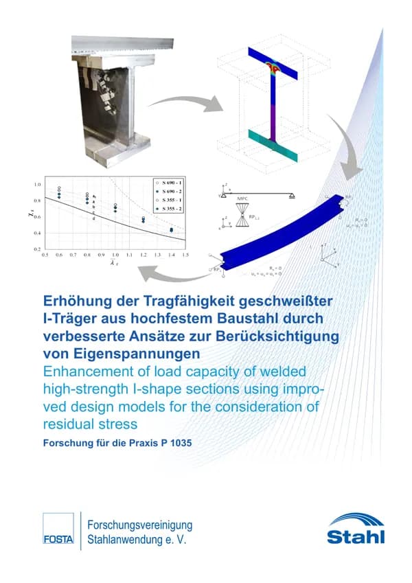
P 1035 - Increasing the load-bearing capacity of welded I-beams made of high-strength structural steel through improved approaches Welded solid wall beams, such as I-beams, are used in many areas of modern steel construction. In contrast to rolled sections, the overall height, cross-sectional shape and sheet thicknesses can be adapted to the load, which results in economic advantages. Nowadays, high-strength fine-grain structural steels with (minimum) yield strengths of up to 690 MPa are increasingly being used. To improve the utilisation of the load-bearing potential of welded profiles made of these steels, there are no suitable models for determining the residual stresses caused by welding on real components. These data are approximated using conservative assumptions. The potential load-bearing capacity of welded structures is therefore generally underestimated. The residual stress assumptions in DIN EN 1993 are based on strong simplifications, e.g. in the context of so-called "equivalent member verifications". These assume the proportionality of the residual stress amplitudes to the yield point. Comparative calculations with a parameterised residual stress model showed possible deviations in the calculated load-bearing capacities over several buckling lines. However, the specifications regarding the buckling line to be applied influence the sheet thicknesses and therefore also the production costs to a considerable extent. As an optimisation strategy, various application-oriented model approaches were therefore developed in this research project, which should enable higher utilisation of load-bearing capacity reserves with the aid of non-linear load-bearing capacity calculations. The research objective was therefore primarily the development and provision of corresponding calculation approaches. To this end, the residual stress state of conventionally welded structures was determined experimentally using the example of I-beams made of two common structural steels, a non-alloy structural steel S355J2+N and a fine-grained structural steel S690QL, which are particularly frequently used in steel construction, and supplemented by numerical welded structure simulations. A simplified calculation model was then derived for further consideration in non-linear load-bearing capacity calculations. The findings are to be incorporated into a corresponding user guide, published by Technical Committee 8 of the European Convention for Steel Structures, and in this respect serve as orientation for a possible future adaptation of the buckling lines in DIN EN 1993-1-1. In the project, the above-mentioned steels were joined in two typical thickness combinations of 25/15 mm and 20/10 mm (chord and web plates) to form large "I-beams" specimens under near-industrial production conditions using metal active gas welding. These produced the typical residual stresses that are present in such beams after production. During welding, the temperature fields were recorded using thermocouples. The residual stresses were determined experimentally after welding by a combination of mechanical disassembly (disassembly method) and subsequent mobile X-ray diffraction (XRD). The influence of the standard industrial flame-cut edge preparation of the sheets on the final residual stress states was also investigated experimentally on small-scale samples. Metallographic analyses (micrographs and hardness measurements) completed the experimental programme of FE 2 (BAM, Berlin). The results showed that a large proportion of the residual stresses had already been removed during mechanical dismantling. However, it was only possible to make a statement about the residual tensile stresses close to the seam by superimposing them with the XRD. The S690QL predominantly showed better behaviour than the S355J2+N, which was expressed, among other things, in lower residual tensile stresses in relation to the respective yield point. The maximum residual stresses were mostly measured in the heat-affected zone (HAZ) of the weld seam, irrespective of the applied line energy or the strength of the base material. The practical construction assumption that the maximum residual stresses can be present at the level of the yield point was only confirmed in individual cases and only for S355J2+N. The experimental results also showed reduced relative residual stress values of the S690QL for the compressive residual stresses. This shows the need for further optimisation when selecting the evaluation approaches for residual stresses on the load-bearing capacity. The measured values generated were subsequently used as input values for the model development and the numerical simulations on I-beams by FE 1 (LSH, Cottbus). The numerical welding simulations were carried out in Simufact.Welding® for the simulation models with a "classic" welding simulation approach and in Ansys® for simplified simulations and approximation approaches. Overall, the models delivered comparable results for the longitudinal residual stresses, although there were some considerable differences in the calculation times. The calculation time could be significantly reduced in all cases by adapting the meshing. However, due to the component sizes used, the application of modelling with solid elements is usually not practicable. For typical beam welds, cross-section models with the assumption of a generalised plane distortion state offer a possible alternative instead. The comparison of the results with the experiments provided predominantly good to satisfactory agreement. The experimentally determined tendencies were correctly predicted in all cases. A comprehensive evaluation of the achievable accuracies has not yet been possible. On the one hand, this was due to the fact that the data density of the results obtained with the decomposition was low. On the other hand, the superimposed results with the XRD provided contradictory statements on the influence of residual stress in parts, particularly in the pressure ranges of interest, which could not be conclusively clarified to date. In addition, any deviations in the simulations were also caused by the underlying material data itself. These corresponded to standard data sets from material libraries. These were scaled uniformly over the entire temperature range. For the S690QL in particular, too few reliable material parameters were available. Corresponding tests could not be carried out as part of this project. Nevertheless, it was possible to gain some important insights into a simplified calculation procedure for taking residual welding stresses into account in load-bearing capacity calculations. Based on the plastic strain patterns determined in the numerical welding simulation models, also known as "residual stress sources", a simplified simulation procedure was proposed and verified. The simplifications introduced were selected with regard to the calculation of only the plastic longitudinal strains or longitudinal residual stresses. The applicability is therefore limited to sufficiently long welded beams with longitudinal seams. Some model modifications for further simplification or model implementation in the structural-mechanical calculation of large components were presented. These investigations are ongoing. Finally, the classification into a possible buckling line is based on a scatter band of load capacities simulated by GMNIA (geometrically and materially non-linear analysis with imperfections) calculations using Abaqus® and Ansys®. The initial hypothesis of a more favourable buckling line of a S690QL compared to the S355J2+N was confirmed by calculation. However, experimental proof by means of corresponding load-bearing capacity tests is still pending. Publication: 2018 Authors: H. Pasternak, B. Launert, T. Kannengießer, M. Rhode
available anytime
€30.00
excl. VAT
Payment by card (Stripe) or invoice (DE, AT, CH). Download link by email: automatically after ordering by card, after order approval for invoice (valid for 30 days). Terms