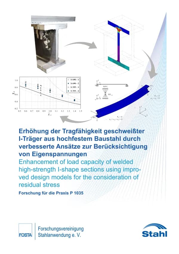
Welded solid wall beams, such as I-beams, are used in many areas of modern steel construction. In contrast to rolled sections, the overall height, cross-sectional shape and sheet thicknesses can be adapted to the load …
P 1035 - Increasing the load-bearing capacity of welded I-beams made of high-strength structural steel through improved approaches Welded solid wall beams, such as I-beams, are used in many areas of modern steel construction. In contrast to rolled sections, the overall height, cross-sectional shape and sheet thicknesses can be adapted to the load, which results in economic advantages. Nowadays, high-strength fine-grain structural steels with (minimum) yield strengths of up to 690 MPa are increasingly being used. To improve the utilisation of the load-bearing potential of welded profiles made of these steels, there are no suitable models for determining the residual stresses caused by welding on real components.
These data are approximated using conservative assumptions. The potential load-bearing capacity of welded structures is therefore generally underestimated. The residual stress assumptions in DIN EN 1993 are based on strong simplifications, e.g. in the context of so-called "equivalent member verifications". These assume the proportionality of the residual stress amplitudes to the yield point. Comparative calculations with a parameterised residual stress model showed possible deviations in the calculated load-bearing capacities over several buckling lines. However, the specifications regarding the buckling line to be applied influence the sheet thicknesses and therefore also the production costs to a considerable extent. As an optimisation strategy, various application-oriented model approaches were therefore developed in this research project, which should enable higher utilisation of load-bearing capacity reserves with the aid of non-linear load-bearing capacity calculations. The research objective was therefore primarily the development and provision of corresponding calculation approaches. To this end, the residual stress state of conventionally welded structures was determined experimentally using the example of I-beams made of two common structural steels, a non-alloy structural steel S355J2+N and a fine-grained structural steel S690QL, which are particularly frequently used in steel construction, and supplemented by numerical welded structure simulations. A simplified calculation model was then derived for further consideration in non-linear load-bearing capacity calculations. The findings are to be incorporated into a corresponding user guide, published by Technical Committee 8 of the European Convention for Steel Structures, and in this respect serve as orientation for a possible future adaptation of the buckling lines in DIN EN 1993-1-1. In the project, the above-mentioned steels were joined in two typical thickness combinations of 25/15 mm and 20/10 mm (chord and web plates) to form large "I-beams" specimens under near-industrial production conditions using metal active gas welding. These produced the typical residual stresses that are present in such beams after production. During welding, the temperature fields were recorded using thermocouples. The residual stresses were determined experimentally after welding by a combination of mechanical disassembly (disassembly method) and subsequent mobile X-ray diffraction (XRD). The influence of the standard industrial flame-cut edge preparation of the sheets on the final residual stress states was also investigated experimentally on small-scale samples. Metallographic analyses (micrographs and hardness measurements) completed the experimental programme of FE 2 (BAM, Berlin). The results showed that a large proportion of the residual stresses had already been removed during mechanical dismantling. However, it was only possible to make a statement about the residual tensile stresses close to the seam by superimposing them with the XRD. The S690QL predominantly showed better behaviour than the S355J2+N, which was expressed, among other things, in lower residual tensile stresses in relation to the respective yield point. The maximum residual stresses were mostly measured in the heat-affected zone (HAZ) of the weld seam, irrespective of the applied line energy or the strength of the base material. The practical construction assumption that the maximum residual stresses can be present at the level of the yield point was only confirmed in individual cases and only for S355J2+N. The experimental results also showed reduced relative residual stress values of the S690QL for the compressive residual stresses. This shows the need for further optimisation when selecting the evaluation approaches for residual stresses on the load-bearing capacity. The measured values generated were subsequently used as input values for the model development and the numerical simulations on I-beams by FE 1 (LSH, Cottbus). The numerical welding simulations were carried out in Simufact.Welding® for the simulation models with a "classic" welding simulation approach and in Ansys® for simplified simulations and approximation approaches. Overall, the models delivered comparable results for the longitudinal residual stresses, although there were some considerable differences in the calculation times. The calculation time could be significantly reduced in all cases by adapting the meshing. However, due to the component sizes used, the application of modelling with solid elements is usually not practicable. For typical beam welds, cross-section models with the assumption of a generalised plane distortion state offer a possible alternative instead. The comparison of the results with the experiments provided predominantly good to satisfactory agreement. The experimentally determined tendencies were correctly predicted in all cases. A comprehensive evaluation of the achievable accuracies has not yet been possible. On the one hand, this was due to the fact that the data density of the results obtained with the decomposition was low. On the other hand, the superimposed results with the XRD provided contradictory statements on the influence of residual stress in parts, particularly in the pressure ranges of interest, which could not be conclusively clarified to date. In addition, any deviations in the simulations were also caused by the underlying material data itself. These corresponded to standard data sets from material libraries. These were scaled uniformly over the entire temperature range. For the S690QL in particular, too few reliable material parameters were available. Corresponding tests could not be carried out as part of this project. Nevertheless, it was possible to gain some important insights into a simplified calculation procedure for taking residual welding stresses into account in load-bearing capacity calculations. Based on the plastic strain patterns determined in the numerical welding simulation models, also known as "residual stress sources", a simplified simulation procedure was proposed and verified. The simplifications introduced were selected with regard to the calculation of only the plastic longitudinal strains or longitudinal residual stresses. The applicability is therefore limited to sufficiently long welded beams with longitudinal seams. Some model modifications for further simplification or model implementation in the structural-mechanical calculation of large components were presented. These investigations are ongoing. Finally, the classification into a possible buckling line is based on a scatter band of load capacities simulated by GMNIA (geometrically and materially non-linear analysis with imperfections) calculations using Abaqus® and Ansys®. The initial hypothesis of a more favourable buckling line of a S690QL compared to the S355J2+N was confirmed by calculation. However, experimental proof by means of corresponding load-bearing capacity tests is still pending.
Payment by card (Stripe) or invoice (DE, AT, CH). Download link by email: automatically after ordering by card, after order approval for invoice (valid for 30 days). Terms
Machine-translated title and description. The document itself is in German.
Digital download
Other parts and editions as well as neighbouring documents of the same series.

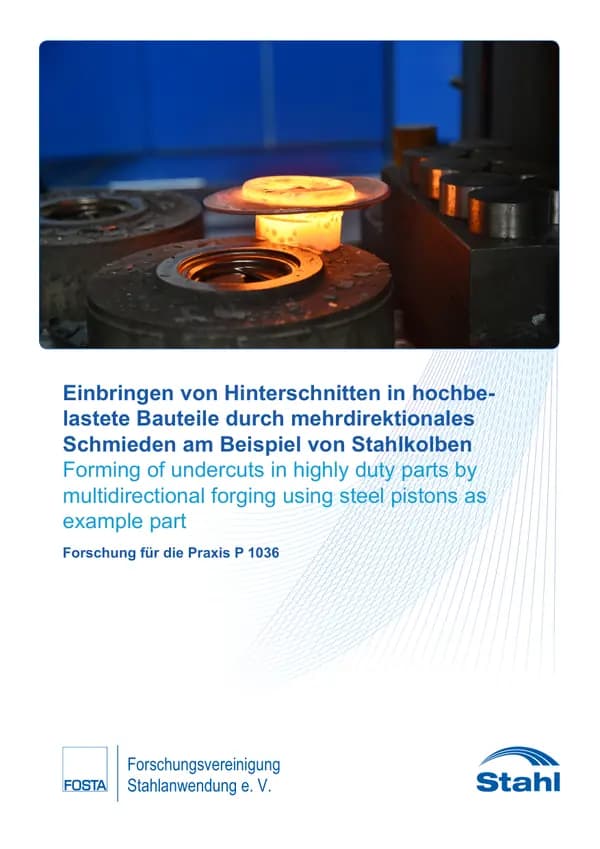
P 1036 - Introduction of undercuts in highly stressed components by multidirectional forging using the example of steel pistons In this AiF project (IGF No. 18162 N), undercut forging was investigated using the example of piston pin bores for steel pistons. In contrast to the conventional forging process for steel pistons, multi-directional forming takes place in the final forming stage, in which the piston pin bores, which represent an undercut, are preformed. To this end, the sequence of stages was first developed virtually with the aid of material flow simulations. A tool concept was then developed to enable undercut forging using a multi-directional tool. With this tool, punches move laterally into the workpiece and deform it further. This tool was designed and manufactured. Various forging tests were then successfully carried out and analysed. The economic efficiency of the process was then assessed and an application guide for the development of undercut forging processes was developed. In this project, the bolt holes in a steel piston could be pre-punched in the forging process for the first time. The advantages of this process are the material savings, improved component properties of the forged part and a faster and simplified reworking process compared to the conventional forging process. The material saving was 5% compared to the standard forging process. The adapted fibre flow in the bore area is likely to be of great importance for the component properties. From an economic point of view, the possibility of accelerated reworking through undercut forging is of the highest relevance. The design of the undercut forging process differs from conventional closed-die forging processes only in the final forming stage. It turned out that the complete punching of the component is associated with too much effort in terms of process technology, so that the pre-punching variant was favoured. The clamping forces required for multi-directional undercut forging are a particular challenge for undercut forging tools. The variants of a force-fit (using springs) and a form-fit closure (using toothing) were investigated. Due to the lower design and production costs, the design of the non-positive locking variant was pursued further. Nevertheless, the positive locking variant promises advantages, as previously impossible forging geometries can be realised, so that future investigations in this direction appear promising. The tests showed that both the retracting and extending movements of the lateral punches require high forces. In particular, the return movement of the plungers requires correspondingly 20 kN must be taken into account and the tools must be dimensioned accordingly. The evaluation of the forging results showed that the forgings were well formed in the undercut area. The fibre flow of the pistons in the bore area turned out to be very favourable and confirmed the simulations carried out previously. Due to a reduced notch effect, more favourable fatigue strength properties can be expected for bores produced using undercut forging. The undercut forging process was used in this project for the insertion of piston pin bores. In general, the process is suitable for introducing a wide variety of undercut geometries into workpieces during forging processes. Publication: 2018 Authors: M. Stonis, J. Ross
available anytime
€30.00
excl. VAT

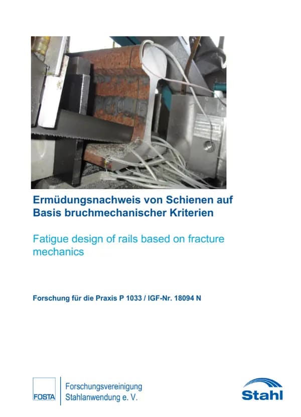
P 1033 - Fatigue analysis of rails based on fracture mechanics criteria In this research project, approaches for the fracture-mechanical description of crack growth in the rail base are developed. For this purpose, finite element simulations are used to show how the stresses from residual stresses, temperature, train passage and structural deformation are distributed in the rail base. The magnitude of the loads to be applied from structural deformation is determined. It can be shown that the stress components can be categorised into three groups according to their distribution in the rail footing, which can subsequently also be found in the determination of the K-factors. Finally, the relationship between torsion and displacement of the bridge head is analysed in more detail. The residual stresses of the rails are determined experimentally. It is shown that the expected residual compressive stresses at the edge of the rail footing also occur in reality. Tensile residual stresses prevail in the centre of the rail base. However, the degree of residual tensile stresses varied greatly depending on the rail grade tested. The large-scale fracture mechanics tests on notched rails show that notched rails of the same quality behave similarly and that fracture mechanics concepts based on cracks in the rail base can therefore in principle describe the cracking of rails. can describe the cracking of rails. However, it is also established that the large-scale tests do not allow any conclusions to be drawn about the actual life expectancy of a railway rail in the track. The notch introduced modifies the test specimens in such a way that the results obtained with them allow conclusions to be drawn about the fracture mechanics model to be used. It is not possible to draw conclusions about the resistance to crack initiation of the individual test specimens. In small-scale fracture mechanics tests, the fracture toughness of the rail steels is determined at the "rail base centre" and "rail base edge" extraction points. It turns out that a purely elastic evaluation of the tests is not expedient. An evaluation for elastic-plastic materials is necessary. It cannot be conclusively clarified whether this necessity is due solely to the material properties of the rail steel or also to the very narrow samples. In order to visualise crack growth using fracture mechanics methods, various approaches are different approaches are shown and the possibility of simulating seasonal dependencies and the interaction of different loads is presented. It is shown that the simulation of individual cracks is very suitable for demonstrating the influence of individual parameters on crack growth. Publication: January 2021 Authors: Prof. Dr.-Ing. M. Mensinger, M.Sc. S. Pessel, Prof. Dr.-Ing. S. Freudenstein, Dr.-Ing. Ch. Simon, Prof. Dr.-Ing. Fischer, M.Sc. N. Schramm, Prof. Dr.-Ing. P. Langenberg
available anytime
€30.00
excl. VAT

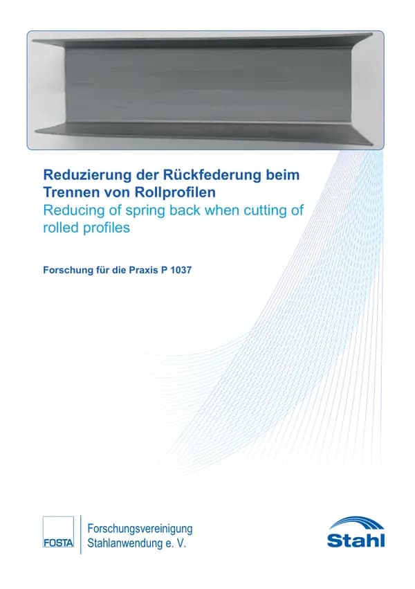
P 1037 - Reduction of springback when cutting rollformed profiles Roll forming is an important process for the production of profiles from rolled starting material. When the profiles are separated after the forming process, residual shear and longitudinal stresses are released which cause the profile ends to collapse or spring open at the separation point. This so-called head bounce leads to deviations in dimensional accuracy, which must be compensated for by additional processing steps. This results in increased system times and therefore higher machine and labour costs. As part of this research project, the state of the art in roll forming companies is first recorded with the help of an anonymised questionnaire. Subsequently, a finite element model will be developed, which enables an exact mapping and prediction of the head crack. With the help of the numerical model, a comprehensive parameter study can be carried out on the basis of the questionnaires. Numerical investigations can be used to identify countermeasures to reduce head bounce and their practical feasibility can be tested experimentally. The results obtained can be used to derive design guidelines for the roll forming process with regard to minimising residual stresses. In the course of the project, the influencing factors of sheet thickness, material strength, forming per station, side rollers, pressure overlay, profile shape, stand spacing, profile height, roll forming strategy, bending radius and roller diameter were determined. The deformation of the profile during cutting allows conclusions to be drawn about the acting stress components. Based on this, several effective countermeasures for reducing the head bounce and their possible applications were developed. Overbending and rebending proved to be universally applicable, as it reduces residual shear and longitudinal stresses. By superimposing compressive or longitudinal stresses, it was possible to reduce one component of the causal stresses in each case. Superimposing longitudinal stresses proved to be effective when both ends of the profile cracked, while superimposing compressive stresses should be applied when the profile collapsed and cracked. Publication: 2017 Authors: P. Groche, M. Moneke
available anytime
€30.00
excl. VAT

P 1032 - Characterisation and modelling of mechanical joints with one-sided accessibility for profile-intensive lightweight construction under crash load The legal regulations to reduce greenhouse gas emissions are prompting the automotive industry to implement consistent lightweight construction. The reduction of CO2 emissions to an average of 95g CO2/km in passenger car traffic by 2020 has been agreed. The vehicle body, which accounts for over 30% of the total weight, offers the greatest potential for implementing lightweight construction, which can be achieved by using high-strength steels in thin sheet thicknesses and other lightweight materials such as aluminium or fibre-reinforced plastics. Due to the profile-intensive mixed construction method, the requirement for accessibility of the joints on both sides cannot be realised throughout the design. Joining technology is increasingly being used for joining tasks that can only be accessed from one side. Methods such as direct screwing (flow-hole moulding screws) and bolt setting are then used here. The aim of the research project is the experimental investigation and numerical modelling of the strength, load-bearing behaviour, deformation and failure behaviour of mechanical joints with one-sided accessibility for profile-intensive lightweight construction under crash load. Using the LWF-KS-2 test technique, characteristic values for the replacement modelling of these connections for crash simulation are to be determined for the joining methods of bolt setting and flow-hole and thread-forming screws (FLS). A substitute model is to be further developed and calibrated for these connections on the basis of the existing substitute model for self-pierce rivet connections. This modelling is to be validated for use in crash simulations using simulations of a sample component test. As part of the research project, tensile tests for a quasi-static and an impact strain rate were carried out for the test materials as an initial test. These form the basis for the subsequent simulation. Following the sampling of the joints planned in this project, characteristic joint values were determined for different set bolt and FLS joints. In order to assess the influence of the position of the joining point in a component and thus the stiffness of the joining parts on the joint behaviour, tests were carried out under shear and peel loading with variation of the specimen geometry. By developing a substitute model and characterisation methodology for joints in profile-intensive lightweight construction, such as flow-hole forming screws and bolting, steel users in design and calculation are able to make reliable statements about the load-bearing capacity of joined steel structures under crash load. This enables the efficient and economical development of joined components made of sten steels for profile-intensive lightweight construction and improves the competitiveness of steel compared to other lightweight construction materials. Publication: 2017 Authors: Dr.-Ing. S. Sommer, Prof. Dr.-Ing. G. Meschut
available anytime
€30.00
excl. VAT
Payment by card (Stripe) or invoice (DE, AT, CH). Download link by email: automatically after ordering by card, after order approval for invoice (valid for 30 days). Terms