Adhesive bonding technology is becoming increasingly important in a wide range of industrial applications due to its potential for joining dissimilar materials. One common application is the adhesive bonding of steel in …
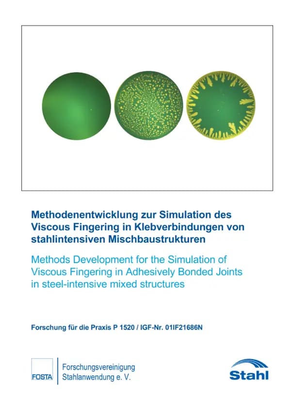
Adhesive bonding technology is becoming increasingly important in a wide range of industrial applications due to its potential for joining dissimilar materials. One common application is the adhesive bonding of steel in combination with aluminium. During the heat curing of the adhesives, the adhesive gap between the components increases due to the different thermal expansion coefficients of the materials. This gap widening occurs predominantly while the adhesive is still liquid and thus leads to a sometimes significant reduction in the original bonded area. The resulting bonded surface has a meandering structure (fingers), the surface area of which decreases as the gap widens.
This structure is "frozen" by the subsequent curing process. Due to the reduced bonding surface, a significantly increased stress build-up and associated damage to the cured adhesive is to be expected. The result is a significantly reduced load-bearing capacity and ageing resistance of the bonded joints. The aim of the project is to develop a method for quantifying the bonding surface actually present in the product in order to improve manufacturing processes and the design for the subsequent operational load case. Both experimental investigations and methods of finite element simulation (FEM) and computational fluid dynamics (CFD) were used for this purpose. The phenomenon known as "viscous fingering" was investigated on various specimens, including Lifting-Hele-Shaw cell, LWF-KS2 specimen, head tension specimen and bridge specimen (with buckling behaviour). In the experimental investigations, the dependence of bond area reduction on the relative displacement of the joining partners could be determined, which can be described by a power approach. This relationship was then implemented in an FEM model in order to carry out strength simulations of joints damaged by viscous fingering. In addition, the reduction of the bonded area due to relative displacements was analysed using CFD in order to reduce the dependence on experiments. The simulated bond area reductions show deviations from the experiments, but these can be compensated for using a correction function. The aim of the research project was achieved.
Payment by card (Stripe) or invoice (DE, AT, CH). Download link by email: automatically after ordering by card, after order approval for invoice (valid for 30 days). Terms
Machine-translated title and description. The document itself is in German.
Digital download
Other parts and editions as well as neighbouring documents of the same series.

P 1521 - Integral sheet pile abutments of modular composite bridges for a time-efficient construction process This report summarises investigations to derive a design concept for an integral frame corner for composite bridges with sheet pile abutments. The composite construction method can be used to produce efficient and economical cross-sections that are capable of covering a large proportion of the spans of today's bridges. The integral construction method, which does not require joints or bearings, leads to lower maintenance costs and reduced external costs of the structure over its life cycle. The use of sheet pile abutments, on the other hand, can significantly reduce the construction costs of the structure. To enable application in the construction industry, a design concept for an integral frame corner with sheet pile abutments is being developed in the FOSTA research project P1521. In order to define the scope of application of the design concept, the existing German infrastructure is first analysed. There is a significant need for refurbishment throughout the entire bridge network. Comprehensive statistics are primarily available for the federal trunk road network, where approx. 80% of all bridges have a span of less than 50 m, which can be covered by the planned concept. In contrast, significantly more individual structures are owned by local authorities and municipalities, and here too short and medium spans dominate. After presenting the boundary conditions of the design concept, the report deals with the implementation and evaluation of various test series of the frame corner. The evaluations of these tests provide insights into the load-bearing behaviour of the cross-sections used and the failure of the respective test specimens. The frame corner is separated into an upper and lower part for a targeted investigation. The results of these small-part tests provide high load-bearing capacities with absorbable moments of 1200 kNm (upper part) and 500 kNm (lower part) with acting loads of 1350 kN (upper part) and 400 kN (lower part). With the help of subsequent numerical calculations, the test results can be further analysed and load paths clearly identified. The knowledge gained from this is used in the subsequent derivation of a design concept. The numerical investigations also identified further influencing parameters that can further increase the performance of the frame corner. In a large-scale test, the entire frame corner consisting of the upper and lower parts is tested. The results of this test are consistent with the results of the previous series of tests; in particular, a higher load on the lower composite dowel bar can be demonstrated. With the help of these results, a design concept for integral frame corners with sheet pile abutments is developed in the final step and presented using a design example of a composite bridge with a span of 45 metres. Publication: April 2024 Authors: Prof. Dr.-Ing. M. Feldmann, K. Wolters, N. Rittich, Dr.-Ing. St. Ivanov, Dr.-Ing. J. Rajasingam
available anytime
€30.00
excl. VAT

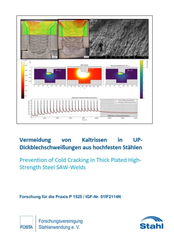
The use of high‑strength steels such as S690 not only enables an ever‑more critical reduction of CO₂ emissions through lower material consumption, but also affords effective cost and weight savings in thick‑walled components. In particular, for wall thicknesses up to 200 mm, submerged‑arc (SAW) multi‑wire welding is common practice owing to its high efficiency. However, when using high‑strength steels, here S690, the risk of hydrogen‑assisted cold cracking (HAC) increases due to their microalloying concepts combined with the high residual stresses generated by the welding process and the elevated component stiffness. Moreover, the substantial intermixing of base and filler metals during SAW welding can give rise to crack‑sensitive microstructures in which diffusible hydrogen is particularly detrimental. No reliable data exist for the hydrogen diffusion coefficients or HAC susceptibility of SAW‑welded thick‑plate assemblies. In particular, the microstructure‑dependent diffusion of hydrogen introduced during the SAW welding process has not been adequately characterized. The aim of the present research was therefore to contribute to cold‑crack‑safe SAW welding of high‑strength thick plates. To this end, different base materials (BMs; S690 TM/QL) were systematically investigated, as these differ especially in their microalloying elements (Ti, Nb, V) and resulting microstructures. Preliminary tests revealed markedly divergent hardness distributions, especially in the final weld pass, suggesting correspondingly divergent diffusion behavior. First, hydrogen pickup from the wire‑flux combination was determined in accordance with ISO 3690. Subsequently, multi‑pass welds were produced both under free‑shrinkage conditions and with external restraint. Detailed microstructural characterization, mechanical‑technological testing and residual stress measurements enabled assessment of crack susceptibility under varied heat‑input regimes (controlled via welding speed). For quantitative description of hydrogen diffusion, the weld metal (WM), heat‑affected zone (HAZ) and base materials were examined by electrochemical charging, carrier‑gas hot extraction (TGHE) and permeation testing. Based on the measured diffusion coefficients, numerical models were developed to evaluate the influence of varying coefficients on the hydrogen distribution within the weld seam. Contrary to the initial hypothesis, no significant differences in hydrogen diffusion rates were measured. Both base‑material classes (QL vs. TM), as well as the WM and HAZ, exhibited characteristic diffusion coefficients for this material type with only minor variations. Together with the very slight differences in residual‑stress magnitudes and mechanical‑technological properties of the welds, these findings indicate a high level of resistance to cold cracking. The minimal differences observed between QL and TM across all investigations thus support the interchangeability of these two steels in production with respect to HAC risk arising from differential hydrogen diffusion. All the objectives of this research project were successfully achieved. Published in: 2026 Authors: D. Czeskleba, Dr. M. Rhode, Prof. T. Kannengießer
available anytime
€30.00
excl. VAT

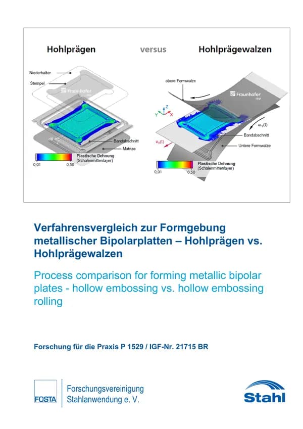
P 1529 - Process comparison for shaping metallic bipolar plates - hollow embossing vs. hollow embossing rollers As part of the research project, fundamental findings on the interactions and limits of hollow embossing rolling of metallic bipolar plates (BPP) made of stainless steel foil were developed. This process, which has been little researched to date, offers the possibility of achieving higher production rates than the hollow embossing and sheet metal pressure forming processes currently in use. The limits of the reproducibility of geometric elements of BPP were determined for the rolling process, the actual achievable production rates were estimated and compared with the results from parallel investigations into hollow embossing. Hollow embossing rolling was initially analysed using FE simulation on the basis of previously defined requirements for a demonstrator geometry, the plant and tool technology. The results were implemented in tool design and process control on the test stand. The simulation model was validated on the basis of the test results and further process improvements were achieved. By analysing process data and measurement results, it was possible to determine which geometric elements can be produced and which cycle times can be realised while maintaining defined tolerances. The results achieved for hollow embossing and hollow embossing rolling are presented as a key result. The focus here is on imageability, image accuracy and production speed. The project results enable SME-strong sectors (suppliers, plant and tool manufacturers) to access the growing market for metallic BPP. Corresponding products and services can be tailored more precisely to the requirements of hollow embossing and hollow embossing rolling. In particular, by focussing the investigations on the determination of process parameters and boundary conditions to be complied with in hollow embossing rolling, the entry into the BPP market was decisively prepared and opened up Publication: March 2024 Authors: Prof. Dr.-Ing. M. Dix, M.Sc. F. Reuther, Dipl.-Ing. S. Porstmann, Dipl.-Ing. (BA) St. Polster, M.Sc. S. Melzer
available anytime
€30.00
excl. VAT
Payment by card (Stripe) or invoice (DE, AT, CH). Download link by email: automatically after ordering by card, after order approval for invoice (valid for 30 days). Terms