Matplus LogoMatplus Shop
/
/
Cart (0)
HomeStoreFOSTAFOSTA Documentation
Topics
Matplus LogoMatplus ShopFollow us on LinkedIn
FOSTA
  • FOSTA Overview
  • FOSTA Documentation
  • Topics
  • Technical Standards
  • Steel-iron worksheets (SEB)
  • Steel and iron usage lists (SEE)
  • Steel-iron delivery terms (SEL)
  • Steel-iron test sheets (SEP)
  • Steel-iron material sheets (SEW)
Legal
  • FAQ
  • Imprint
  • Cookie Policy
  • Privacy Policy
  • Legal Notice
  • Withdrawal policy
  • Withdraw from contract
  • General Terms and Conditions

Payment by card (Stripe) or invoice (DE, AT, CH) · Digital delivery: download link to your PDFs by email, automatically after ordering by card, after order approval for invoice; valid for 30 days.

© 2026 Matplus Shop. All rights reserved.

Header
FOSTA

P 1408 - Experimental investigation of wind pressure distribution in open and closed circular cylindrical silo structures and tanks

Silos and tanks are used in industry for the storage of bulk materials and liquids. With a circular cross-section, the vertical side walls are loaded rotationally symmetrically by the filling material, resulting in a …

Content

Publication
September 2023
Authors
M.Sc. N. Wieczorek, Dr.-Ing. J. Unglaub, Univ.-Prof. Dr. sc. techn. K. Thiele

Silos and tanks are used in industry for the storage of bulk materials and liquids. With a circular cross-section, the vertical side walls are loaded rotationally symmetrically by the filling material, resulting in a uniform tensile stress in the circumferential direction. This makes it possible to produce thin-walled silos and tanks in steel construction with a wall thickness of just a few millimetres. When empty or partially filled, however, there is a risk of stability failure due to the asymmetrical wind load in the circumferential direction, so that the wind is often the decisive design situation. The existing approaches in the Eurocode for describing the wind pressure distribution do not adequately cover some design situations, particularly for silos and tanks within a group.

Show full description

As part of this research project, extensive and systematic wind tunnel tests were carried out on models of circular cylindrical silos and tanks with different H/D (height/diameter) ratios. The aim was to further develop the existing design models in order to create a safe and at the same time economical design basis. The experimental investigations carried out are divided into two parts. In the first part, tests were carried out on individual models with eight different H/D ratios (H/D = 0.3 - 4.0). The effects of the three-dimensional flow around the cylinder and the change in pressure distribution as a function of the cylinder slenderness were investigated. The suction stresses in particular vary greatly as a function of H/D and increase with increasing cylinder slenderness. The maximum stresses (both pressure and suction) occur at around 70 % of the cylinder height. In addition to the external pressure distributions, the internal pressure distributions were determined for cylinders open at the top. It was shown that a greater negative pressure (퐶푝푖 ≈ -0.8) occurs with slim silos (H/D ≥ 1) than the value of -0.6 recommended in the Eurocode. In the second part, pressure measurements were carried out on single and double-row vessel groups consisting of two to six cylinders. The tests were carried out on the models with H/D = 0.5 and 2.0. The direction of flow β and the distance between the cylinders S/D (gap width/diameter) were varied. In total, tests were carried out on more than 200 container groups. The main results are, on the one hand, a significant increase in the positive pressure range on the side facing the wind with decreasing S/D, particularly on the centre cylinder in a row of three with a vertical direction of flow (β = 90°). The magnitude of the compressive stresses increases with the cylinder slenderness H/D. On the other hand, for the slender silo models (H/D = 2.0), a considerable increase in the lateral suction stresses on the side of the upstream cylinder with free flow around it at β = 120° - 135° and S/D = 0.1 - 0.25 was determined. The main findings were processed in the form of design recommendations and a load model was developed to describe the wind pressure distribution of individual silos and tanks as well as container groups. The objective of the research project was achieved.
P 1408 - Experimental investigation of wind pressure distribution in open and closed circular cylindrical silo structures and tanks
Zum Zoomen hovern
€30.00excl. VAT

Payment by card (Stripe) or invoice (DE, AT, CH). Download link by email: automatically after ordering by card, after order approval for invoice (valid for 30 days). Terms

P 1408 - Experimental investigation of wind pressure distribution in open and closed circular cylindrical silo structures and tanks—
€30.00
Machine-translated title and description. The document itself is in German.

What's included

✓

Digital download

Similar documents

Other parts and editions as well as neighbouring documents of the same series.

  • Thumbnail
    FOSTA

    P 1410 - Extension of DIN EN 1993-1-10 to offshore conditions for notch cases on hollow section connections for jacket construction

    P 1410 - Extension of DIN EN 1993-1-10 to offshore conditions for notch cases on hollow section connections for jacket construction To date, there are no standardised rules for the design of jacket foundations in offshore applications with regard to material selection and toughness requirements. The aim of this project is therefore to transfer the concept of toughness verification established in civil engineering to jacket foundations in offshore applications on the basis of rules for material selection. Using fracture mechanics concepts for brittle fracture resistant component design, a reference geometry is first identified, crack assumptions are made and a crack propagation calculation is carried out based on the determined load spectrum. This results in the fracture mechanics limit state analysis, which is used to derive toughness requirements. This also takes into account the influences of strain rate, cold forming and the specific offshore operating conditions. The fracture mechanics concept of material selection established in the field of building and bridge construction is thus successfully transferred to jacket foundations. In addition, the project is the first to develop a method for deriving toughness requirements for the component in a specific application with the aid of a damage mechanics model. The modified Bai-Wierzbicki model is used, which can model plasticity, ductile damage and brittle failure as a function of stress state, strain rate and temperature. To ensure comparability between fracture mechanics and damage mechanics, the same boundary conditions are considered. Damage mechanics also derives toughness requirements, confirms the results of fracture mechanics and demonstrates its conservative calculation method. Publication date: November 2022 Authors: Prof. Dr.-Ing. Kühn, P. Krahl, M.Eng, Univ.-Prof. Dr.-Ing. S. Münstermann, D. Lenz, M.Sc.

    available anytime

    €30.00

    excl. VAT

    View details →
  • Thumbnail
    FOSTA

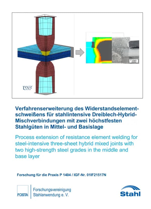
    P 1404 - Process extension of resistance element welding for steel-intensive three-sheet hybrid mixed joints with two high-strength steel grades in the centre and base layer

    P 1404 - Process extension of resistance element welding for steel-intensive three-sheet hybrid mixed joints with two ultra-high-strength steel grades in the centre and base layer Against the backdrop of dwindling resources, climate policy requirements and simultaneously high customer demands in terms of comfort and safety, the automotive industry is forced to reduce the environmental impact of its vehicle fleets. In addition, the trend towards autonomous driving is increasing the number of technical devices to be moved in cars. As the vehicle body accounts for a considerable proportion of the total weight of the vehicle, various lightweight construction measures are being realised at this point. Mixed construction with form-hardened steels has established itself here, whereby a steel-intensive bodyshell is combined with various aluminium outer skin components. Both steel and aluminium-intensive lightweight construction can be realised using conventional joining technologies, as existing mechanical joining systems are capable of producing similar and dissimilar joints. Thermal joining processes enable cost-efficient same-type joints between two or three body panels. Dissimilar joints are often produced by mechanical joining processes, as process-reliable joints are possible in combination with adhesives. Due to thermal, electrical and chemical incompatibilities between steel and aluminium, conventional resistance spot welding (WPS) is not an efficient joining solution for dissimilar joints. Thermal-mechanical joining processes are increasingly coming into focus, as they utilise the advantages of mechanical and thermal joining technology to realise dissimilar mixed joints. Resistance element welding (RW) offers great potential for creating steel-aluminium combinations. The object of the research project is the fundamental investigation of two-stage resistance element welding for the production of three-sheet hybrid mixed joints. The investigations include fundamental experimental and simulative analyses with regard to different material-thickness combinations. Sample rivets are produced on the basis of an auxiliary joint geometry designed using numerical simulations, suitable welding parameters are determined by means of welding tests and the joint formation is evaluated. Adequate joint strengths are identified in investigations into the mechanical load-bearing capacity. A demonstrator component is realised to prove the feasibility of three-layer WES connections. The knowledge gained contributes to a deeper understanding of the process of two-stage WES of three-ply hybrid joints and opens up a wide range of applications in the steel processing industry, especially for small to medium-sized companies, with enormous potential for weight savings in car body construction. The results provide users with a basis for the design, economical production and improvement of three-layer WES joints, The aim of the research project was achieved Publication: 2024 Authors: G. Meschut, M. Heitmann, V. Haak

    available anytime

    €30.00

    excl. VAT

    View details →
  • Thumbnail
    FOSTA

    P 1403 - Detection of preload losses in bolts based on electromechanical impedance spectra

    P 1403 - Detection of preload losses in bolts based on electromechanical impedance spectra Bolts in HV joints are preloaded as planned, whereby the operational safety of these bolted joints is significantly influenced by the level of preload force. However, generating and maintaining the required preload force before and during operational loading is not always sufficiently successful. A loss of preload force due to automatic loosening during the operational loading of bolted connections can be caused by two different causes, namely loosening due to settling or creeping or automatic loosening of the bolt and/or nut. Preloaded bolts relax due to the settling of the surfaces of the clamping package (levelling of surface roughness, creep of the coating). Creep occurs when the interfacial pressure of the pressurised surfaces is exceeded. These effects are time-dependent and lead to a reduction in the preload force. However, failure is also frequently due to loosening and/or automatic loosening during operation, particularly in the case of bolted connections subject to vibration. This is synonymous with the complete or partial loss of the preload force, which in many cases results in a fatigue fracture of the bolt. In this research project, a method was therefore developed that enables cost-effective, continuous monitoring of the bolt force using electromechanical impedance spectra as part of structural health monitoring (SHM), for example. As an introduction to the topic, Chapter 2 provides a brief overview of the state of the art, the current methods for measuring preload forces in bolted joints are discussed (Chapter 2.1) and the possibilities and objectives for the preload of bolts based on the currently applicable standards and guidelines are presented (Chapter 2.2). Building on this, the main features of measurements based on electromechanical impedance spectra are presented in chapter 2.3. In particular, it explains what electromechanical impedance spectra are, how they are generated and what is required for the measurement of electromechanical impedance spectra. This part of the report is aimed in particular at readers who have had little or no previous contact with electromechanical impedance spectra. Furthermore, a brief overview of the test specimens used in the project is given using an example of an M16x50 test specimen equipped with measurement technology. Subsequently, the factors that are important for the measurement of electromechanical impedance spectra are discussed in relation to the present application using exemplary FE calculations; the influences of preload force, temperature, sensor damage and adhesive layer on the electromechanical impedance spectra are explained. Building on this, Chapter 0 presents the (physical) background to the measurement of electromechanical impedance spectra. The relationships between the formation of electromechanical impedance spectra and the influences of preload force, temperature and sensor damage, which were already presented in the previous chapter 2.3, are explained in detail. By deriving causalities, it can be shown in which parameter ranges the influences of preload force, temperature, sensor damage and adhesive layer on the impedance spectra are valid. Chapter 2.5 explains the statistical analysis of the generated data in accordance with Military Handbook 1823, focusing primarily on the procedure and objective of the statistical analysis and the choice of method for the analysis. Chapter 3 first explains the basics of the experimental investigations (Section 3.1) and, building on this, the results of the preliminary investigations (Section 3.2). The spectra used to analyse preload force, temperature and sensor damage were determined on the basis of the preliminary tests. The series measurements are then presented and analysed (section 3.3). Firstly, it is shown how a loss of preload force and its magnitude can be reliably recognised on the basis of the evaluated measurements at a constant temperature. The compensation of the temperature influence is carried out in chapter 3.4. Finally, a statistical analysis is used to show the magnitude of the preload losses, which can be recognised in at least 90 % of cases with a confidence level of 95 %. Chapter 3.5 presents the tests for detecting damage in the measurement chain and develops a method that enables the detection of typical damage. The additional tests carried out on HV screws M72x380 are briefly presented in Chapter 3.6. The results of the ultrasonic measurements carried out are then discussed in Chapter 3.7. Publication: February 2022 Authors: Univ.-Prof. Dr.-Ing. D. Pak, Dr.-Ing. D. Sahm, Univ.-Prof. Dr.-Ing. C.-P. Fritzen, A.-L. Dreisbach, M.Sc

    available anytime

    €30.00

    excl. VAT

    View details →
  • Thumbnail
    FOSTA

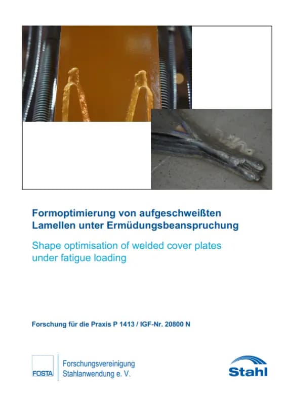
    P 1413 - Shape optimisation of welded-on lamellae under fatigue loading

    P 1413 - Shape optimisation of welded-on lamellae under fatigue loading A weight-optimised design to avoid an unnecessarily increased consumption of resources is becoming more and more important in terms of economic efficiency and especially against the background of significantly increased procurement prices. Localised reinforcement measures, so-called reinforcement lamellas, are used for this purpose in the construction industry and also in other steel processing sectors. These locally increase the cross-section to match the external stress. In the case of alternating stresses, such as those caused by traffic passing over steel bridges, these structures must be designed to withstand fatigue failure. Here, the very notch-sharp end of the lamella leads to a poor notch case classification, which represents the resistance side in the fatigue analysis. The aim of the research project was therefore to make the end of the lamella significantly less notchy by optimising its shape and production. To this end, various disc shapes and designs were analysed numerically in a first step as part of the preliminary investigations. Experimental investigations were then carried out on selected variants. By varying the disc shape and different designs with, for example, tapered weld seams, the two most promising shapes and designs were then selected for the main tests as part of the preliminary investigations. Influencing factors such as the material quality, the design and the installation situation were analysed experimentally as part of the investigations. In addition, the transferability of the small component tests to larger dimensions was checked by means of large component tests. The design of the tapered lamellae with tapered weld seams proved to be very notch resistant and led to a significant increase in fatigue strength in both the untreated and post-treated states compared to conventional standard moulds. In addition, the parameter range of the experimental tests was extended by a comprehensive numerical parameter study and the design of the lamella shapes was additionally optimised by accompanying numerical models. As part of the project, a design recommendation for tapered weld seams with tapered lamellae was developed on the basis of the nominal and notch stress concept. In order to enable applicability in practice, additional design recommendations were developed that contain quality requirements with regard to the design. The aim of the research project was achieved. Publication: February 2024 Authors: A. Dürr, J. Roth, M. Mensinger, N. Rausch, M. Wilnhammer

    available anytime

    €30.00

    excl. VAT

    View details →
€30.00excl. VAT

Payment by card (Stripe) or invoice (DE, AT, CH). Download link by email: automatically after ordering by card, after order approval for invoice (valid for 30 days). Terms

P 1408 - Experimental investigation of wind pressure distribution in open and closed circular cylindrical silo structures and tanks—
€30.00